Although the noise performance of modern camera sensors at high ISO settings has improved dramatically over the past decade, photographers who demand clean, noise-free images must still wrestle with the problem of eliminating high ISO noise. One strategy is to simply avoid shooting at high ISO settings whenever possible by lowering the ISO and extending the exposure time. The question that is often raised is – “what settings should I use to obtain a proper exposure”? This is not a particularly difficult question to answer, however the answer becomes infinately more useful and valuable if one understands the reasoning behind the solution. This article is my take on solving this problem.
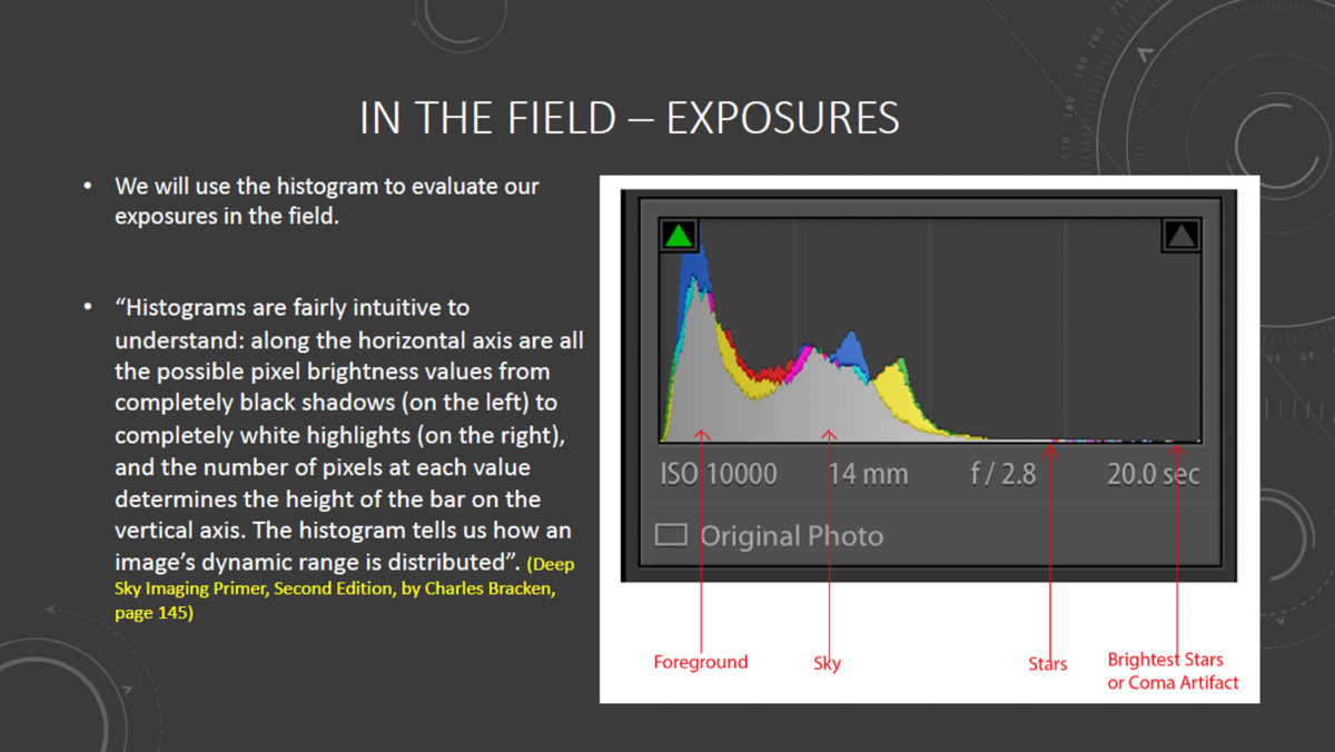
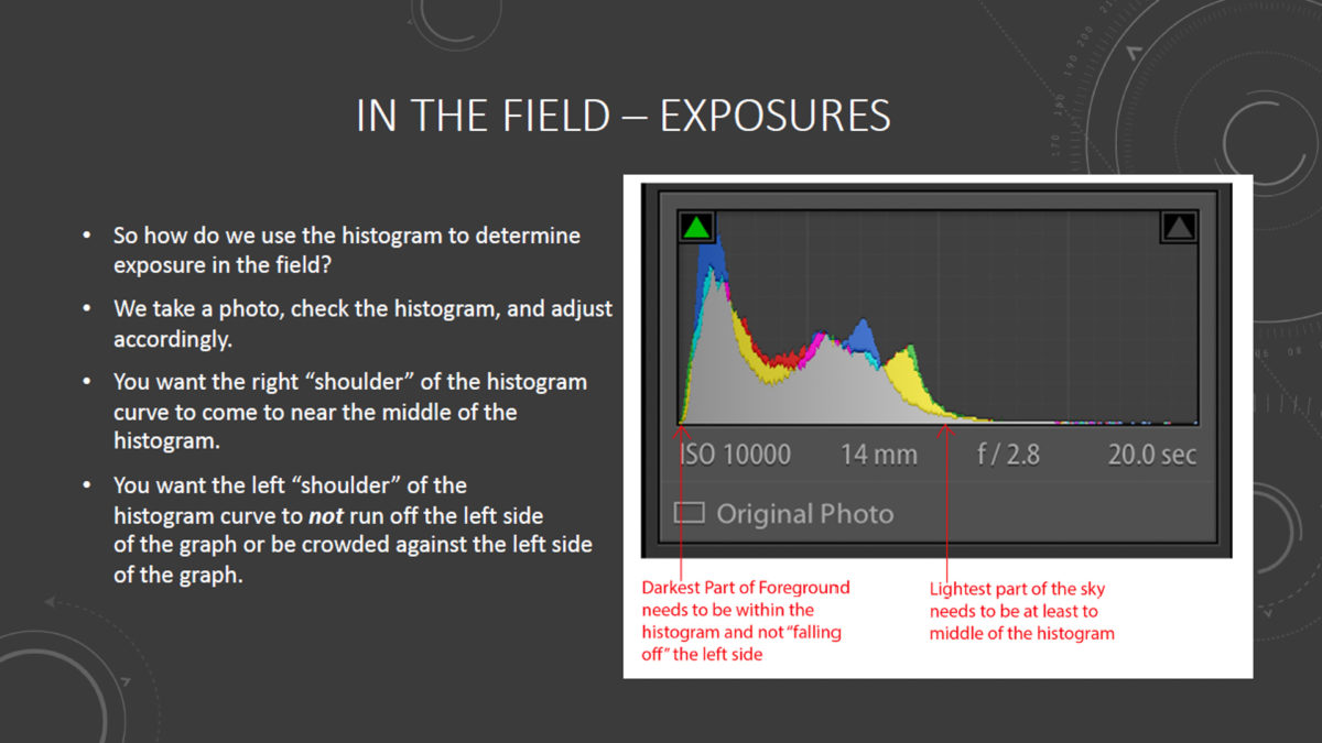
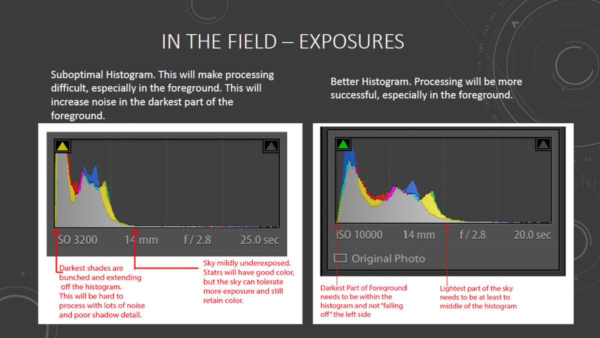
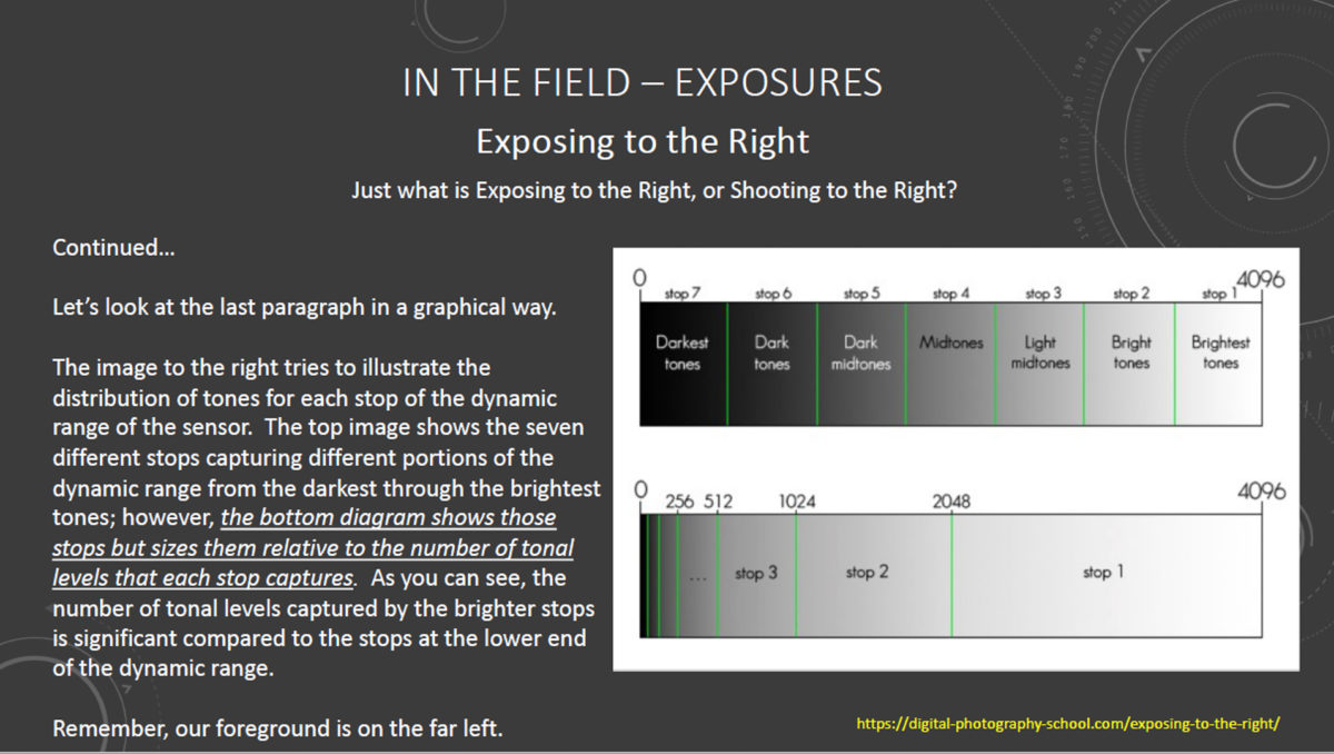
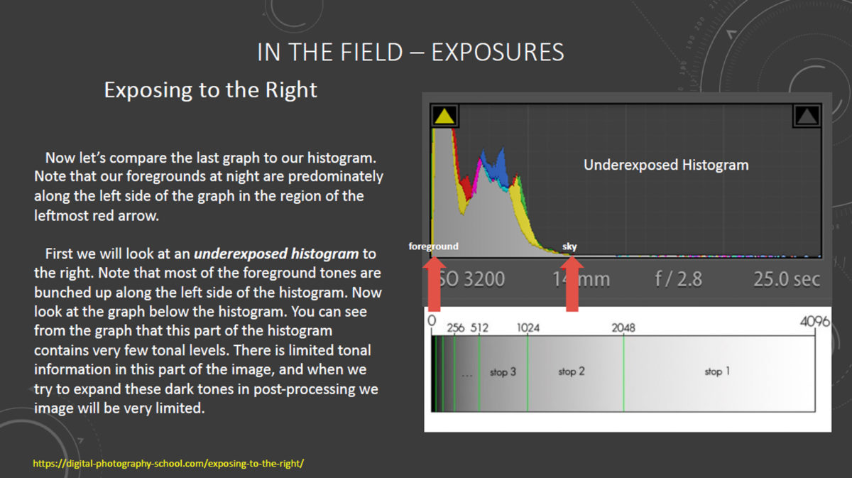
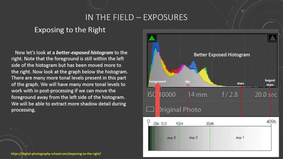
It is important to understand what a proper exposure actually is in the context of low-light or nighttime photography. A proper exposure is NOT determined by how the image looks when reviewed on your LCD screen after exposure. Your LCD display will fool you every time – it is not determinative of a proper exposure. What IS determinative is what is shown on your histogram, as this creates a graphic representation of the data actually captured and recorded by your camera sensor. So let us begin by learning what the histogram is, and how it can be effectively used in the context of our night photography. The following graphics explain the concepts we need to know in order to determine a proper exposure.
NOTE – Click images to view full size (Tablet or PC)
DETERMINING LENS APERTURE (f STOP)
So now that we know what a proper night exposure histogram looks like, how can we determine the settings to create an image with a good histogram, which also minimizes high ISO noise in our image?
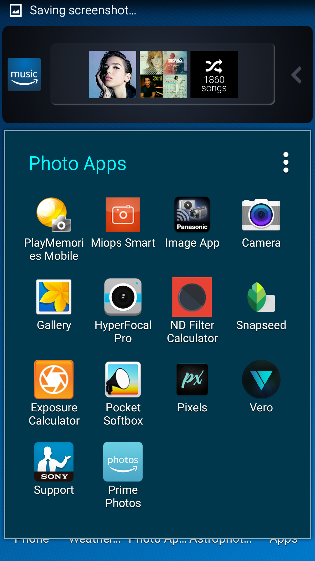
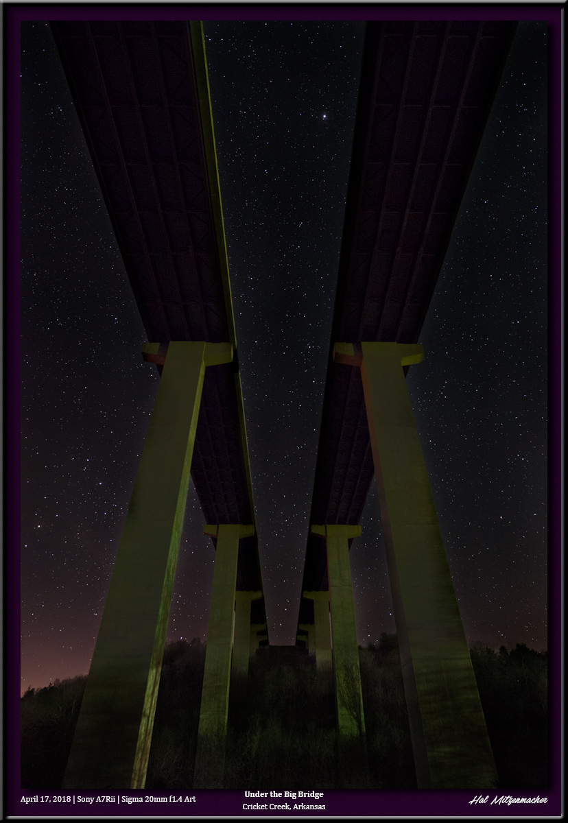
The first exposure setting I prefer to establish is the lens aperture. This is a balancing act- the wider the aperture, the shorter the exposure time needs to be, however, the wider the aperture, the shallower the depth-of-field (DoF) that is produced. My usual procedure is to select the widest aperture that still gives me the necessary DoF my composition requires. To do this, I refer to one of the readily-available Hyperfocal Distance Calculator apps that resides on my smartphone. A test shot taken with the lens focused at the calculated hyperfocal distance will allow me to review the exposure to be certain the my subject matter is entirely in focus. If not, I will reduce the aperture (thus increasing the depth-of-field), refocus at the new calculated hyperfocal distance, and try again. When I am satisfied with the focus at the selected aperture, I can then move on to determining ISO and exposure time.
DETERMINING ISO AND EXPOSURE TIME
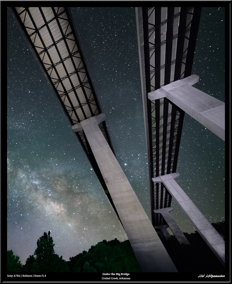
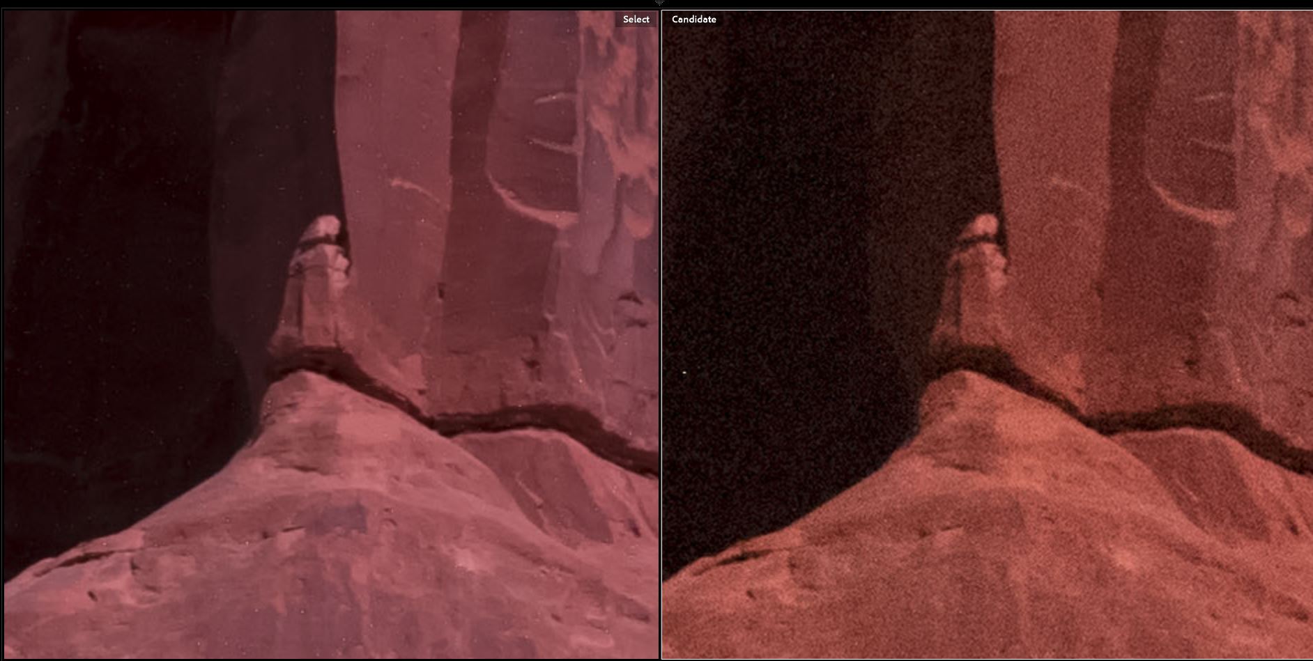
Ideally, I would like to shoot my long-exposure at my camera’s native ISO, which in the case of the Pentax K1 is ISO 100 (this is a common native ISO, however your camera may vary). Shooting at the native ISO will minimize random noise in the image. the following image comparison shows the extreme noise difference between an ISO 6400 shot and an ISO 100 shot, which is the whole point of doing a low ISO, long-exposure in the first place.
So let us figure out what exposure time we need in order to get a proper histogram if we were to shoot at ISO 100. We could do this with guesswork or trial and error, but that would be frustrating and wasteful of our precious shooting time. Fortunately, there is a quick, simple technique that can be employed to help us figure out our exposure.
Step 1
Set your ISO to 6400. Set your exposure time to 15 seconds. Take a test exposure and check the histogram in your image review. If the histogram is too far to the left, increase the exposure time. If the histogram is too far to the right (possible, but unlikely in most circumstances) decrease the exposure time. Take another test shot and evaluate the histogram. Continue adjusting the exposure time and taking test shots until you are satisfied that you have a proper histogram. Make note of these exposure settings.
Step 2
You will now use the previously noted exposure settings to calculate an equivalent long-exposure time at ISO 100. There are two ways to do this. One way relies on any of the readily-available smartphone Exposure Calculator apps. There are many available, you may already have one at your disposal. You just enter the test exposure information, enter the desired ISO, and the app tells you how long the new exposure should be at ISO 100 (or any other ISO you choose).
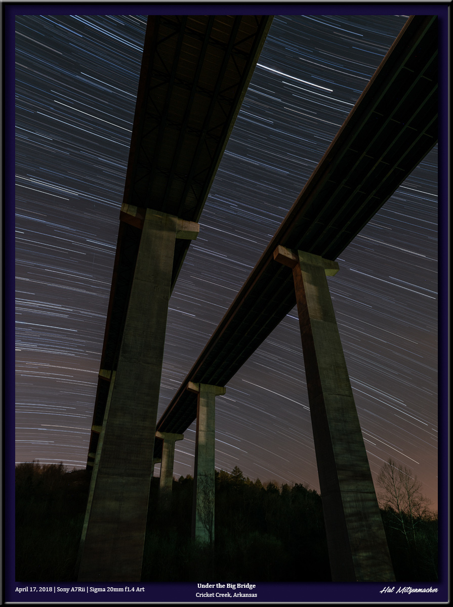
A second method utilizes the “Six Stop Rule.” Simply stated, this rule says that the number of SECONDS of exposure at ISO 6400 will equal the number of MINUTES of exposure at ISO 100. For example, if the test exposure that produced a good histogram was 15 seconds at ISO 6400, the equivalent exposure will be15 minutes at ISO 100.
FINAL THOUGHTS
While shooting a long-exposure at native ISO is the ultimate goal, it is not always absolutely necessary to shoot at that low an ISO. Perhaps, like me, you prefer to shoot long-exposures using the Long-Exposure Noise Reduction (LENR) function available with your camera. In that case, the total camera time will be double the exposure time (since the camera is taking a second exposure with the shutter closed in order to accomplish a dark frame subtraction, which cancels out hot-pixel noise). Therefore, a 15 minute exposure actually takes 30 minutes of field time, which may be unacceptable to you. Perhaps you are shooting a panorama or mosaic, in which case you may simply not have enough time to capture all of the long-exposures at ISO 100. Under these circumstances, you might well consider shooting your long exposures at ISO 200, ISO 400 or even higher. The choice is yours, and your decision will be informed by your knowledge of the characteristics of your camera and the circumstances you are faced with on any given night. but now you have a framework for quickly determining what exposure settings to use when shooting a long-exposure night photograph.