
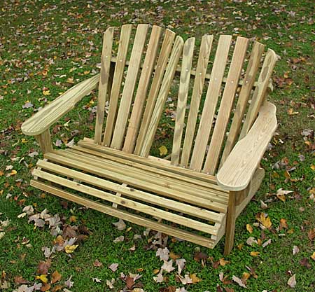
In my last post (Adirondack Loveseat Project) I promised to upload plans for the loveseat you see in the photograph above. So here they are.
The plans presented here are an amalgam of ideas garnered from several sources, including woodworking books, Internet websites, and of course, my own experimentation. I have completed several of these loveseats to date, so I can attest to the fact that these plans indeed work as advertised.
Here are some quick comments and suggestions before presenting the plans.
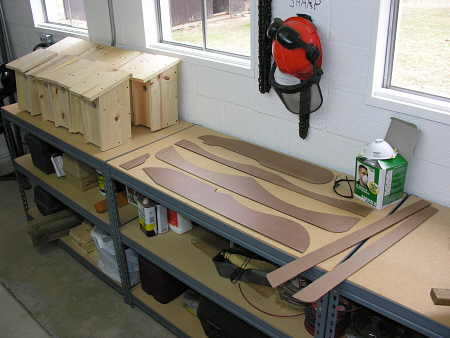
After building the first prototype and assuring myself that the plans were workable, I created a set of templates (using 1/8″ hardboard) seen in the photograph above. Because of the templates, I can build additional loveseats relatively quickly, but it is not necessary to go through this step if you are only intending to build one loveseat. The plans can be plotted out directly on the workpiece if you choose. If you take this route, however, I would suggest that for the seat supports (3 in all) you complete one piece, then use that piece as a template for the remaining two parts, thereby ensuring that all three end up with matching profiles.
The lumber that I have chosen for this project is 5/4 x 6″ x 8′ pressure treated deck boards. This material is durable, readily available at most lumberyards or home improvement centers, and inexpensive. It is also laden with chemicals of various pedigree, so it is imperative to take precautions when working with this material, especially if working in an enclosed area.
Notice in the photograph above, beside the templates, are a pair of tight fitting safety glasses and a box of respirators. If you work with pressure treated lumber, these are the minimum safety precautions you should take. If you do work in a shop environment, you might consider doing more.
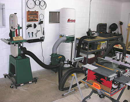
Because pressure treated lumber is a material I will be utilizing in my projects for the foreseeable future, I invested in a dust collection system, pictured above. It requires a bit of ingenuity to set up, and an additional equipment expense, but what price can you place on your lungs, anyhow?
Now, on to the plans, as promised.
Adirondack Style Loveseat PlansÂ
(Clicking on thumbnail opens full-size window, which can then be printed.)
Parts List
1 – Upper Back Support
1-Â Lower Back Support
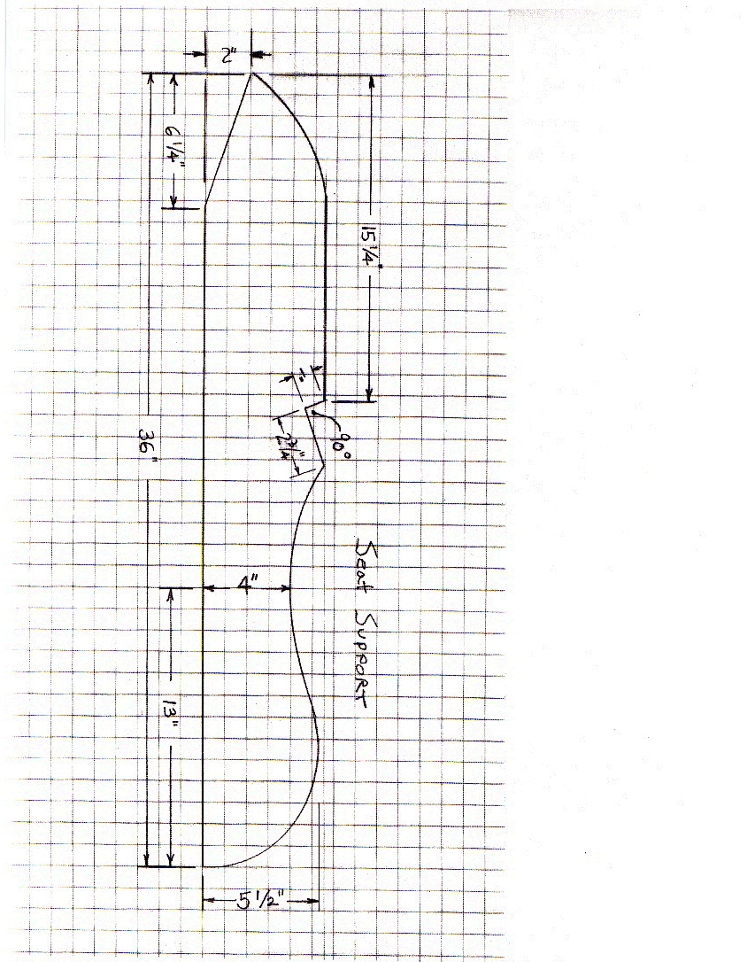
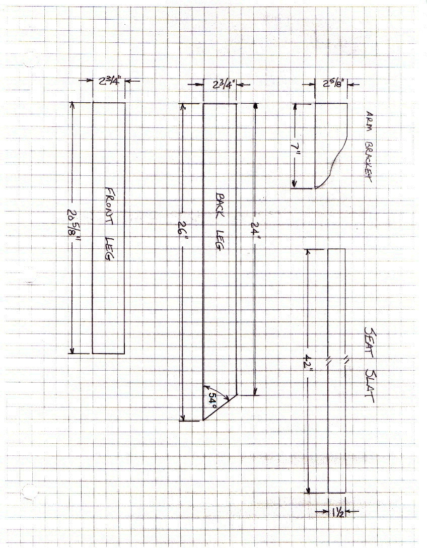
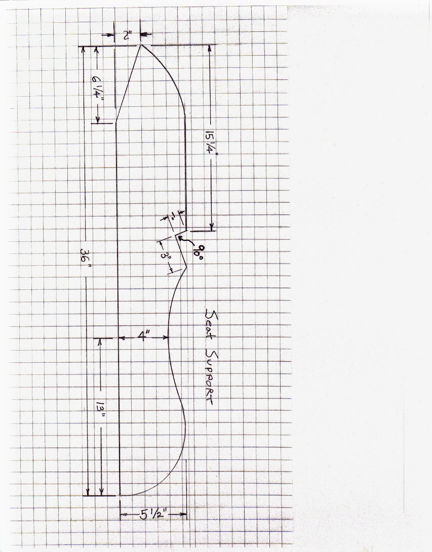
3 – Seat Supports
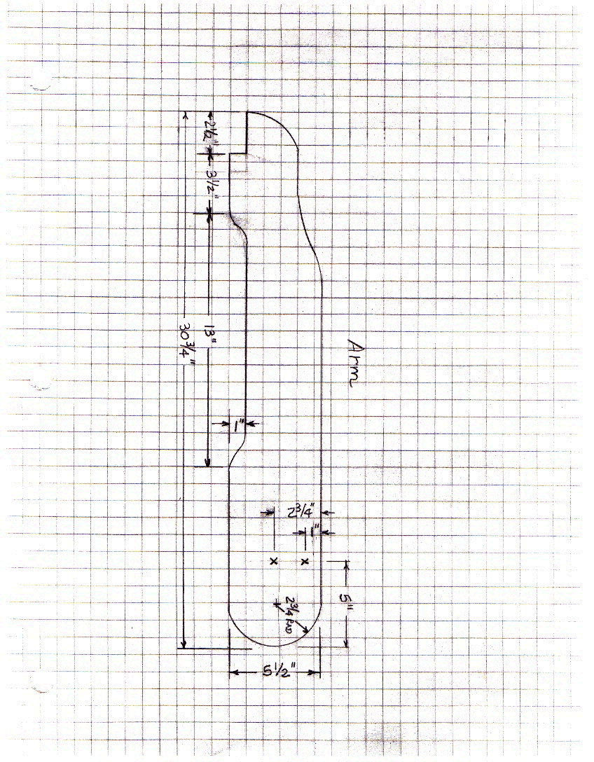
2 – Arms
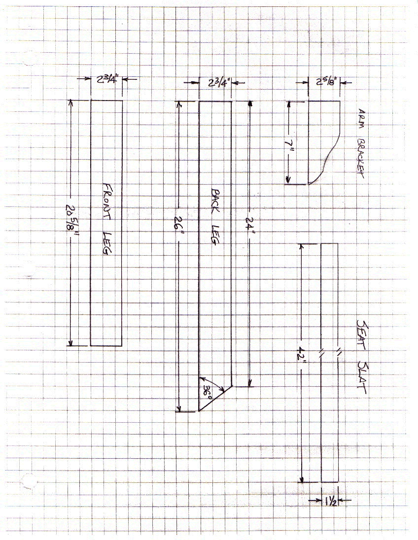
2 – Front Legs
2 – Back Legs
2 – Arm Brackets
9 – Seat Slats
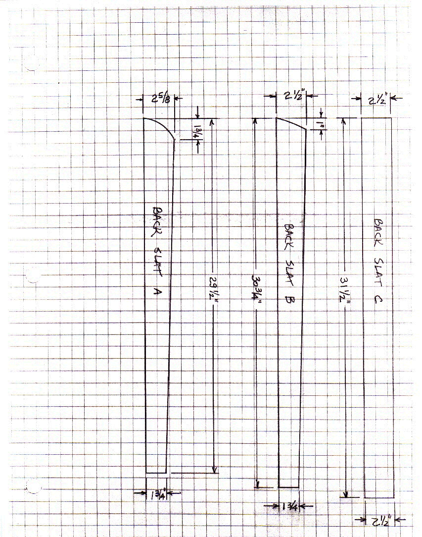
4 – Back Slats (A)
4 – Back Slats (B)
4 – Back Slats (C)
#8 x 2″ deck screws
Construction Notes
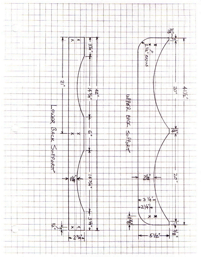
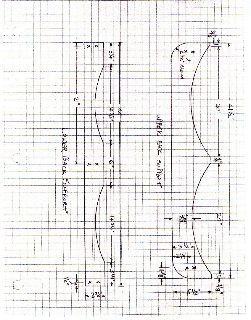
A. Cut all parts as per drawings. A table saw is highly recommended, as many parts require rip cuts. Because this project has many curved parts, a band saw is also helpful, but a saber (jig) saw will suffice.  The only curves that are dimensionally critical are the curves that occur on the upper and lower back supports.
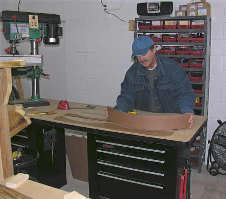
Use a flexible piece of scrap material or a metal rule to lay out the curves in the back supports, bending this guide until it aligns with the points indicated in the plans, as you can see me demonstrating in the photograph above. With this exception, all other curves in the plans are decorative only, so use your sense of artistry to lay these curves out by eyeball.
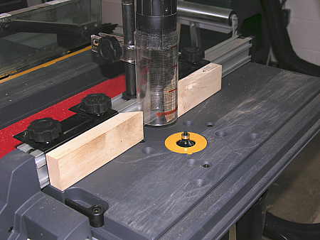
B. If you have a router or router table (as in the photo above), you can use a 1/4″ ball-bearing roundover bit to ease the exposed edges of the slats and arms. If no router is available, a power sander or hand-sanding can serve the same purpose.
C. Sand surfaces of all parts.
D. Drill and countersink all pilot holes, which are marked with an X in the drawings (to avoid splitting the lumber, I suggest drilling pilot holes in the mating pieces also before driving the screws).
E. On each seat support, make a mark 5-3/4″ in from the front, on the bottom face of the support. Make another mark 2″ in from the back, also on the bottom face of the support. These marks will be used to align the front and back legs to the outer seat supports.
F. Using the straight front edge of your workbench (or a straight board as a gauge), position one front leg over one seat support, aligning the bottom of the leg and the flat area of the seat support with the straight edge. Position the front of the leg with the mark you made in step E (5-3/4″ in from the front), being certain that the leg is perpendicular to the straight edge. To double check the accuracy of your positioning, the angle formed by the intersection of the front leg and the bottom of the seat support should be 75 degrees. When you are sure the positioning is correct, screw the leg to the seat support using three #8 x 2″ deck screws.
G. Repeat step F for the other front leg, remembering that this side is not identical, but a mirror image of the side completed in step F.
H. Attach the right and left sides you have just created to the lower back support, screwing the lower back support into the notches at the tops of the seat supports.
I.  Screw the remaining seat support to the center of the lower back support.
J. With the chair assembly on a flat surface, use a square to position the back legs square to each seat support. Align the rear of the back legs with the mark you made in step E (2″ in from the back). Note that, unlike the front legs, which are attached to the outside of the seat supports, the back legs attach to the inside of the seat supports. Clamp the legs, then screw them to the seat support.
K. Attach the two arm brackets to the outside of the front legs, flush with the top of the leg, using two #8 x 2″ deck screws for each bracket.
L. Position the arms on top of the arm brackets, with the notch on each arm fitting snugly against the back leg. Attach the arms to the front legs, using #8 x 2″ deck screws. Level each arm by measuring the distance from the arm to the floor at the front of the chair, and use that measurement to position the back of the arm relative to the back leg. Clamp, and secure with two #8 x 2″ deck screws on each arm.
M. Position the upper back support on top of the back legs, being sure the inner edge of the support is flush with the inner edges of the legs. Secure with #8 x 2″ deck screws.
N. Position one back slat (A) on the outermost edge of the curves in the upper and lower back supports, with the bottom edge flush with the bottom of the lower back support. You will notice that because the upper and lower curves are not identical in radius, the bottom of the slat will not sit flush against the surface of the lower back support.Â
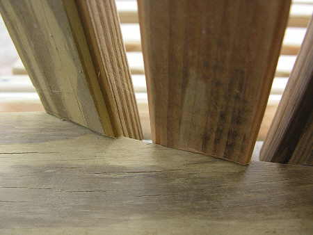
The solution to this problem is to create a notch in the bottoms of back slats A and B, as shown in the photograph above, using a rasp or by sanding. The slats will now sit flush against both the upper and lower back supports. Clamp a back slat A to each outer edge, and fasten top and bottom with #8 x 2″ deck screws. Position the remaining slats, being sure to space them equally apart at both the tops and bottoms. Secure with #8 x 2″ deck screws.
O. Place a seat slat against the back slats, at the rear of the loveseat. Fasten with three #8 x 2″ deck screws. Place another seat slat flush with the bottom edges of the seat supports, at the front of the loveseat. Fasten with three #8 x 2″ deck screws.
P. Fasten the remaining seven seat slats to the seat supports, spacing the slats evenly along the supports. Fasten each seat slat with three #8 x 2″ deck screws.
Q. Apply any finish or water sealer of choice, allow to thoroughly dry, and enjoy your new super-comfy Adirondack style loveseat.

