Devil’s Rope Museum

Ouch!!  A sting from a normal sized scorpion can be very painful – I know this from personal experience.  But can you imagine encountering a foot-long scorpion?  I have come face-to-face with one of these giants, as evidenced by the following photograph.

I ran across this specimen (metallica hadrurus arizonensis) while visiting the Devil’s Rope Museum in McLean, Texas.  And if this one isn’t large enough to frighten you, how about a scorpion the size of a human being?  It must have existed, because I read about it on the Internet – specifically, here.

But back to the Devil’s Rope Museum,  which claims to be the largest barbed wire historic museum in the world, and is the topic of this post.   I visited this museum while passing through McLean, Texas, shortly before writing a  previous post  regarding my pathetic little collection of barbed wire and fencing tools. 

McLean, Texas (pop. 830) lies along the path of old Route 66, which I happened to be exploring this past Fall.  After a delightful lunch stop at the Red River Steakhouse  (a place with real cowboys and cowgirls seated at the tables, excellent rib eye steaks, and great fresh cobblers included with all meals), the Devil’s Rope Museum caught my eye as I was departing town.  Grabbing my camera, I headed inside to see what might be on display.

The museum offers a variety of exhibits related to barbed wire and fencing, as well as barbed wire art, such as the scorpion (as seen in the first photograph), and the woven wire hat, seen here.

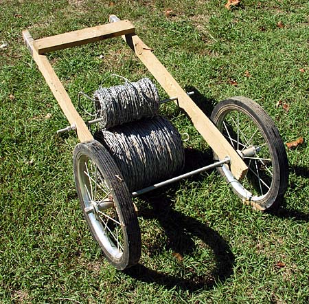
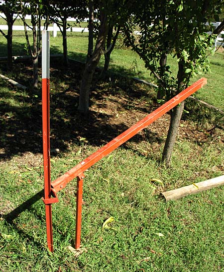
This photograph shows one example of the portable wire fence fabrication machines the museum has on display.

In times past, many rural ranchers utilized the top wire of their barbed wire fencing to transmit electrical communications signals (telegraph, telephone, etc.) from point to point.  These ranchers soon became well-versed in the concept of electrical insulators, and began using any appropriate items or materials that might have been on hand at the moment, as seen in the preceding photo.

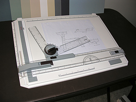
In those parts of the plains states where timber was in short supply, substitute materials would be found for the construction of fence posts.  The photo above shows a clever seat/hand drill device used to bore holes in stone fence posts – a daunting task, indeed!

This is an uncommon earth auger designed to be powered by a vehicle’s 12 volt electrical charging system.  Perhaps these tools will make a comeback as a result of $4.00/gallon gasoline.

This is just a small sample of the thousands of styles of barbed wire that the Devil’s Rope Museum has on display throughout the building.

Here are some of the various designs and sizes of fencing staples that are on display, along with an explanation of what the different types of staples are used for.

The museum hosts a nice size collection of branding irons and brands, including this example of early land grant brands.

Because the Devil’s Rope Museum is located along old Route 66, the facility includes a small, but nice exhibit pertaining to the Texas portion of Route 66.

On display within this section of the museum is this mock-up of a 1940’s era diner, with all of the appropriate appliances and accouterments.

You may remember reading my previous post about the Big Texan Steak Ranch in Amarillo, Texas.  If so, you may be interested to know that the cast model steer on display at the museum (seen above) is the steer that graced the original location of the Big Texan.  If you look back at that previous post, you will see that the current steer replica is vastly larger than this original one.

In addition to this small sampling of the exhibits at the Devil’s Rope Museum that I have depicted above, I also viewed a special photographic collection pertaining to the Dust Bowl era that afflicted the mid-west region in the 1930’s.  Seeing the disaster that took place, and the human devastation that resulted was a heart breaking experience.  Because I did not take photographs of the exhibit (for copyright reasons),  I have included  this link  to a website containing similar photographs.  It is well worth a click over to the site.

Mys-deer-ious Mystery

Back in September, 2007, I wrote a post entitled A Head Shed? , wherein I mused about finding a complete deer skull (including the racks) in one of our pastures.  I opined that the buck may have been taken down by a pack of coyotes, whereas several commentators posited that the deer may have been struck by a vehicle, or wounded by a hunter far from our property, eventually to wander over here to die.


Well, that post was back in September, 2007.  This past March (2008), while hiking along in the “back forty”, Gracie happened upon this buck skeleton (pictured above).  The bones were picked clean, and mostly scattered in the immediate area.

Since that second skeletal find in March, I have located two additional complete skulls on the property, bringing the grand total to four – all discovered within the past six months.

Considering that the closest paved road is about 2 miles distant from where these remains were found, I think it is highly improbable that all the deer were struck by a distant automobile and wandered, dazed and disoriented, onto our property to die.  One incident, perhaps – but four?  I doubt that vehicular mishaps explain my finds.

It seems strange to me that each of the skeletons I have found is a full grown buck.  I wonder if there is any significance to this, or is it just an improbable coincidence? 

A bad toupee?

Anyhow, no matter what the cause of the demise of these unfortunate Odocoileus virginianus, don’t you think this is an astonishingly bad toupee?

California Poppy Preserve

After months of absence from the blog-o-sphere due to a Wordpress installation that prevented the posting of photographs, a software update has now put me back in business, so to speak.  It’s catch-up time, so I will begin with photographs recently taken at the California Poppy Preserve, located in California’s high desert Antelope Valley.

 Poppies in field

When the conditions are favorable, springtime brings on a spectacular display of these orange wildflowers, drawing tourists and locals alike to witness the beauty of a desert in bloom.

The poppy fields stretch in all directions, creating a remarkable panorama at ground level.  I can only imagine what the poppy fields must look like from the air!

The delicate beauty of the California Poppy is indeed a sight to behold.  This Wikipedia article on the California Poppy contains much useful information.

I’ll leave you with this last photograph, while I try to figure out how to use this new version of Wordpress to post several months worth of backlogged material!

Loveseat Plans

Adirondack Loveseat

In my last post (Adirondack Loveseat Project) I promised to upload plans for the loveseat you see in the photograph above.  So here they are.

The plans presented here are an amalgam of ideas garnered from several sources, including woodworking books, Internet websites, and of course, my own experimentation.  I have completed several of these loveseats to date, so I can attest to the fact that these plans indeed work as advertised.

Here are some quick comments and suggestions before presenting the plans.

Templates

After building the first prototype and assuring myself that the plans were workable, I created a set of templates (using 1/8″ hardboard) seen in the photograph above.  Because of the templates, I can build additional loveseats relatively quickly, but it is not necessary to go through this step if you are only intending to build one loveseat.  The plans can be plotted out directly on the workpiece if you choose.  If you take this route, however, I would suggest that for the seat supports (3 in all) you complete one piece, then use that piece as a template for the remaining two parts, thereby ensuring that all three end up with matching profiles.

The lumber that I have chosen for this project is 5/4 x 6″ x 8′ pressure treated deck boards.  This material is durable, readily available at most lumberyards or home improvement centers, and inexpensive.  It is also laden with chemicals of various pedigree, so it is imperative to take precautions when working with this material, especially if working in an enclosed area.

Notice in the photograph above, beside the templates, are a pair of tight fitting safety glasses and a box of respirators.  If you work with pressure treated lumber, these are the minimum safety precautions you should take.  If you do work in a shop environment, you might consider doing more.

Dust Collection

Because pressure treated lumber is a material I will be utilizing in my projects for the foreseeable future, I invested in a dust collection system, pictured above.  It requires a bit of ingenuity to set up, and an additional equipment expense, but what price can you place on your lungs, anyhow?

Now, on to the plans, as promised.

Adirondack Style Loveseat Plans 

Drawings       Drawings      Drawings

Drawings       Drawings

(Clicking on thumbnail opens full-size window, which can then be printed.)

Parts List

1 – Upper Back Support

1-  Lower Back Support

3 – Seat Supports

2 – Arms

2 – Front Legs

2 – Back Legs

2 – Arm Brackets

9 – Seat Slats

4 – Back Slats (A)

4 – Back Slats (B)

4 – Back Slats (C)

#8 x 2″ deck screws

Construction Notes

A.  Cut all parts as per drawings.  A table saw is highly recommended, as many parts require rip cuts.  Because this project has many curved parts, a band saw is also helpful, but a saber (jig) saw will suffice.   The only curves that are dimensionally critical are the curves that occur on the upper and lower back supports.

Laying out curves

Use a flexible piece of scrap material or a metal rule to lay out the curves in the back supports, bending this guide until it aligns with the points indicated in the plans, as you can see me demonstrating in the photograph above.  With this exception, all other curves in the plans are decorative only, so use your sense of artistry to lay these curves out by eyeball.

Roundover bit in router table

B.  If you have a router or router table (as in the photo above), you can use a 1/4″ ball-bearing roundover bit to ease the exposed edges of the slats and arms.  If no router is available, a power sander or hand-sanding can serve the same purpose.

C.  Sand surfaces of all parts.

D.  Drill and countersink all pilot holes, which are marked with an X in the drawings (to avoid splitting the lumber, I suggest drilling pilot holes in the mating pieces also before driving the screws).

E.  On each seat support, make a mark  5-3/4″ in from the front, on the bottom face of the support.  Make another mark 2″ in from the back, also on the bottom face of the support.  These marks will be used to align the front and back legs to the outer seat supports.

F.  Using the straight front edge of your workbench (or a straight board as a gauge), position one front leg over one seat support, aligning the bottom of the leg and the flat area of the seat support with the straight edge.  Position the front of the leg with the mark you made in step E (5-3/4″ in from the front), being certain that the leg is perpendicular to the straight edge.  To double check the accuracy of your positioning, the angle formed by the intersection of the front leg and the bottom of the seat support should be 75 degrees.  When you are sure the positioning is correct, screw the leg to the seat support using three #8 x 2″ deck screws.

G.  Repeat step F for the other front leg, remembering that this side is not identical, but a mirror image of the side completed in step F.

H.  Attach the right and left sides you have just created to the lower back support, screwing the lower back support into the notches at the tops of the seat supports.

I.  Screw the remaining seat support to the center of the lower back support.

J.  With the chair assembly on a flat surface, use a square to position the back legs square to each seat support.  Align the rear of the back legs with the mark you made in step E (2″ in from the back).  Note that, unlike the front legs, which are attached to the outside of the seat supports, the back legs attach to the inside of the seat supports.  Clamp the legs, then screw them to the seat support.

K.  Attach the two arm brackets to the outside of the front legs, flush with the top of the leg, using two #8 x 2″ deck screws for each bracket.

L.  Position the arms on top of the arm brackets, with the notch on each arm fitting snugly against the back leg.  Attach the arms to the front legs, using #8 x 2″ deck screws.  Level each arm by measuring the distance from the arm to the floor at the front of the chair, and use that measurement to position the back of the arm relative to the back leg.  Clamp, and secure with two #8 x 2″ deck screws on each arm.

M.  Position the upper back support on top of the back legs, being sure the inner edge of the support is flush with the inner edges of the legs.  Secure with #8 x 2″ deck screws.

N.  Position one back slat (A) on the outermost edge of the curves in the upper and lower back supports, with the bottom edge flush with the bottom of the lower back support.  You will notice that because the upper and lower curves are not identical in radius, the bottom of the slat will not sit flush against the surface of the lower back support. 

Notch in back slats

The solution to this problem is to create a notch in the bottoms of back slats A and B, as shown in the photograph above, using a rasp or by sanding.  The slats will now sit flush against both the upper and lower back supports.  Clamp a back slat A to each outer edge, and fasten top and bottom with #8 x 2″ deck screws.  Position the remaining slats, being sure to space them equally apart at both the tops and bottoms.  Secure with #8 x 2″ deck screws.

O.  Place a seat slat against the back slats, at the rear of the loveseat.  Fasten with three #8 x 2″ deck screws.  Place another seat slat flush with the bottom edges of the seat supports, at the front of the loveseat.  Fasten with three #8 x 2″ deck screws.

P.  Fasten the remaining seven seat slats to the seat supports, spacing the slats evenly along the supports.  Fasten each seat slat with three #8 x 2″ deck screws.

Q.  Apply any finish or water sealer of choice, allow to thoroughly dry, and enjoy your new super-comfy Adirondack style loveseat.

Adirondack Loveseat Project

UPDATE: The loveseat plans and guidance can be found HERE

You may recall a previous post wherein I declared a goal of erecting 100 bluebird nesting boxes around our property.  The progress on that project has been satisfactory.  To date, I have built 65 nesting boxes:  50 have been erected along our trails, 3 were given to others, and 12 remain in my shop, awaiting my ambition to pound more t-posts into the ground.

Since then, I have taken a short break from building nesting boxes in order to complete a couple of other quick projects.  First, there was the benchtable, the subject of my last post.  And now, I have just finished this Adirondack style love seat.

Adirondack style loveseat

Well, it really isn’t finished, because to truly be called finished, I must apply some kind of finish to the love seat – then it will be, quite literally,  finished.  But it’s close enough.

I intended to build this love seat from plans obtained from a book Retta purchased some time ago.  After buying the necessary materials for the project, the next step was the preparation of the templates I would use to produce uniform, accurate parts.  It turns out the author of the book, or the editor, or both, did not check the construction plans for accuracy and/or completeness.  It soon became apparent that many critical dimensions and cutting angles were omitted from the plans.

Contoured seat bottom of Adirondack style loveseat

Determined to build this love seat, I pressed forward, figuring (correctly, as it turned out) the worst that could happen would be a little wasted time and lumber.  The photograph above shows the contoured seat bottom assembly that had to be built, but because the plans offered little assistance, a lot of guess work (and wasted lumber) went into building this part of the seat.

Rear of Adirondack style loveseat

The love seat is made from 1″ stock (5/4 x 6″ pressure treated deck boards), and feels quite sturdy.  It is designed with a series of three seat supports and substantial bracing, as you can see from the picture above.

Contoured loveseat back slats

The reason I decided to build this seat, even though the plans were deficient, was that the design promised to be extremely comfortable, with the contoured seat bottom that I mention before, as well as the contoured seat back, which is evident in the photograph above.

Even though I spent a lot of extra time, and wasted some lumber experimenting in order to get the seat angles just right, the project turned out to be well worth the effort.  This is one of those pieces that, once seated, you just don’t want to get up out of, due to it’s very comfortable design.  Now that I have a working sample in front of me, I will build accurate templates, so that I can build several at a time and scatter them around the property (along with all the bluebird nesting boxes and benchtables ;)

 ___________________________

In commenting on the Benchtable post, Karl suggested that I upload plans for the benchtable, so that they may spread throughout the Ozarks.  As it happens, I recently ran across a wonderful little drafting board while at Grizzly Industrial  in Springfield, Missouri.

Portable drafting board

Now, once I brush up on my mechanical drafting skills, I’ll try to figure out how to post the plans on-line for those who may wish to build something in their spare time.

A Benchtable

Although my last blog post indicated that this current post was to be on the topic of barbed wire, that will have to wait, as I would rather show you my new benchtable (rhymes with vegetable), the latest project to emerge from my shop.

A picnic spot near the catfish pond

There are many locations around the property where Retta and I like to picnic, such as the woods behind the catfish pond.  Because we use this area to picnic regularly, we have “furnished” it with a fire ring,  a rehabilitated glider, and a picnic table.

Full-sized picnic table

This is the heavy, full-sized (8′ long) picnic table that I built a few years ago (note to self – picnic table needs a new coat of stain).  It is a sturdy table, and works just fine for a picnic, but as you surely know, picnic tables are not comfortable for sitting any length of time.  Hence the steel glider, which provides comfy seating for extended periods of leisurely reflection and conversation.  As Pablo, at Roundrock would surely agree, nice, comfy seating is a necessity for peace-of-mind and happiness here in the Ozarks.

Now, there are many locations (perhaps 20 or so) around the property where Retta and I like to stop and rest while on a hike, to simply sit and watch the grass growing under our feet, or the birds flying overhead.  But where to sit?  One needs a comfy seat to sit in (unless one likes to sit in the sometimes damp, sometimes tick-laden grass).

New benchtable

To provide comfy-seating around the property, I found construction plans for a wooden bench in a home-project book, and after altering some dimensions and angles to suit my tastes, built a prototype, which is pictured above.

The bench is made from treated “2 by” lumber, is six feet long, and is heavy enough that it will “stay put” in the winds that sometimes scream down the hollers of the Ozarks.  Most important, the dimensions and angle of the bench combine to create a very comfortable seat.

Rear view of benchtable

In this rear-view of the bench, you can see the stout (and rather unorthodox) supporting structure that forms the back of the bench.  Besides adding heft to the bench, this assembly allows the back of the bench to swivel up and lock in a horizontal position, which converts the bench to a picnic table.  And that is the real beauty of this bench design.  It is a bench, but it is also a table.  And so, I call it a “benchtable”.

The benchtable locked into “table” position

This photograph shows one of the bench back/table top support brackets.  The back/top pivots on the lower, fixed hex-bolt.  The upper bolt (without a nut) locks the top into position.  To restore the picnic table to it’s bench form, simply pull out the upper bolt and lower the back/top assembly.

Benchtable in “picnic” mode

Even though this opens to only what amounts to a picnic “half-table”,  it is sturdy and still provides room for a portable BBQ and a couple of hungry picnickers.

Now that I have built one prototype, I have identified a few little details that I want to change, and I will then get to work producing templates, so that I can easily duplicate the parts.  My goal is to build enough benchtables to place at strategic spots on the property so that Retta and I will have no excuse not to sit back and watch the grass grow.

Benchtable in “loafing” mode

:) As I am doing here :)

Devil’s Rope

Devil’s rope – an ominous sounding moniker.  But anyone who has worked with barbed wire will tell you that it is an appropriate term for this most unforgiving ranch fixture.  Devil’s rope (AKA barbed wire) will lash out at you at the least provocation.  It will lacerate your skin just as efficiently as it rips your new blue jeans to shreds.  Want to know if someone really lives on a farm or ranch?  Just look at their hands and arms for the telltale scars that come from working with this fiendish fencing material.  No scars apparent?  Urban cowboy.  Period.

 Short section of barbed wire fence needing repair

So you can appreciate the slight groan that escaped my lips as Retta informed me that a small section of barbed wire fence (seen above) needed repair.  This was a task that couldn’t wait, however.   This section of fencing keeps our horses within their grazing pasture, and out of our pond and nearby hayfield.  At best, barbed wire fencing is a safety concern around horses, but sagging, loose barbed wire is a disaster waiting to happen.  So off to work I went.

A makeshift wire caddy

I gathered up my small collection of barbed wire fencing tools to accomplish this repair chore.   Spools of barbed wire are both heavy and unwieldy, so it is helpful to use some type of caddy to facilitate handling the spools.  Commercial caddys are available at farm & ranch stores, but since I had two solid-rubber, spoked, ball-bearing wheels laying around, I fashioned a makeshift caddy using the surplus wheels, along with some scrap lumber and a couple of pieces of threaded rod.

A few fencing tools

The basic tools I use are seen in this photograph.  A bolt cutter will cut through wire, nails and fencing staples easily, so it is handy to have one on hand for repair work.

The t-post driver is a heavy tool that is used to pound t-post into the ground (you can see a picture of one in action in this previous post).  I cannot tell you exactly how much mine weighs, but I can describe a magical property that all t-post drivers possess – with each successive t-post that you install, the driver gets heavier.  It will get heavier and heavier, until you can’t lift it anymore!

The yellowish device is a wire stretcher, which allows the barbed wire to be drawn up tight and firm.  The small red-handled tool is called a fencing pliers, and is very handy to have in your pocket as you make repairs.  A spool of smooth wire can be utilized in a variety of ways, as can a good assortment of fencing staples (for trees and wooden posts) and t-post clips.

Last, but certainly not least – don’t forget a stout pair of leather gloves to help protect your hands from the thousands of sharp, cunning barbs that await you on the malicious spool of wire you are about to work with.

T-post puller

If you are careful about positioning your t-posts correctly before pounding them into the ground, you may never need to use the t-post extractor pictured above, however,  if you are like me, it will soon become a well-worn tool in your arsenal of fencing supplies.  It is a simple device that grips the nubs projecting from the t-post, and through the use of a fulcrum base, exerts tremendous upward pressure onto the t-post, thereby extracting it from the ground.  Now, you can re-position it and pound it back into the ground, where you should have put it in the first place :)

The reason I have chosen to ramble on about devil’s rope will become apparent with my next post, so check back soon…

A Nice Way to Kill Some Time

Cliff House Inn and Restaurant

A few day ago Retta and I had to leave her vehicle at the local Ford dealer for some maintenance, which was going to take a few hours for the dealership to complete.  We decided to kill the time by sightseeing in our local area, which took us south along Arkansas Scenic Byway 7, which is always a lovely and picturesque drive.

Because we hadn’t eaten anything prior to leaving the house, we thought it would be a fine idea to partake of breakfast at the Cliff House Inn, a well-known (among locals) diner located in a spectacular location along the scenic route. 

Cozy balcony overlooking the canyon

Besides good food at a fair price, the main draw of the Cliff House Inn is the view that can be seen from the dining room and from the casual balcony, shown in the photograph above.

Why travel all the way to Arizona?

The Cliff House Inn overlooks a scenic canyon, which, according to the sign above, is the deepest canyon in the Ozarks.

Wonderful view from Cliff House Inn balcony

While this canyon certainly cannot compete with the Grand Canyon in scope and drama, it is still a beautiful and very delightful sight to view while savoring a meal at the Inn.  In the photograph above, you can see the view from the balcony on a day when a typical Ozarks fog bank filled the canyon.  By the time we had finished our breakfast, the fog had dissipated, offering a clear view of the surrounding hills and valleys (hollers, as they’re known around here).

Large geode for sale at Mystic Cavern gift shop

After breakfast at the Cliffhouse Inn we traveled back toward town.  Northern Arkansas is home to over 4700 identified caves, owing to the Swiss cheese-like geology of the schist formations that form the Ozarks.  Along the way we passed one of these caves, Mystic Cavern, which operates daily guided cave tours, and so we elected to kill some more time by taking a cavern tour.  As we waited for the guided tour to begin, we browsed the gift and rock shop on the premises, where we saw this amazingly large amethyst geode from Brazil (asking price – $2700).

Formations inside Mystic Cavern

Inside Mystic Cavern you can see all of the various types of cave formations you would expect to see in such an environment.  It was well worth the time and minor effort involved for us to see this cavern.

Between breakfast at the Cliff House Inn and a tour of Mystic Cavern, we thought it was time to start heading back to town, but not without one more quick stop along the way.

Stopover at Buffalo National Scenic River

We would be crossing a section of the Buffalo National River, a scenic waterway administered by the U.S. National Park Service as the first U.S. National River.  The Buffalo River is a superb and popular river for float trips.  Besides the solitude and seclusion the river offers, the main draw is the pristine beauty of the crystal clear water gently flowing along cliffs and rock embankments like the one shown in the photograph above.  When the water is calm, it is hard to tell where the water begins and the rock ends.  We wouldn’t think of driving by the Buffalo River without stopping to take a look, which is exactly what we did before returning to town to pick up Retta’s vehicle from the dealership.

It is a very nice feeling knowing that we can enjoy such a wonderful and scenic day by just driving around the very area we choose to make our home.

A Head Shed?

Antler sheds found in fields

It is not unusual for me to find deer antler sheds around my fields and pastures, such as the ones pictured above.  I try to keep a sharp eye out for them in the fall, particularly when I am using the tractor to bush-hog our fields.  Why the sharp lookout?

Antler point extracted from tractor tire

In the photograph above there is a small tine from a deer antler that I keep on my desk.  It reminds me of the day I found it, lodged in the sidewall of a perfectly good rear tractor tire.  Seeing as this tine cost me about $400.00, I figure that it can at least serve as a paper weight for a short period of penitence.

A running gag

We find the sheds so often that I thought I would begin to mount them and display them on a wall.  I was in Bass Pro Shop in Springfield, Missouri about 5 years ago, when I saw an antler mounting kit for sale at a reasonable price.  I bought one, and soon had a pair of shed antlers proudly on display above my office desk, as you can see in the photograph above.

Something looked peculiar with the antlers I had hanging on the wall, but I couldn’t quite put my finger on what it might be.  Then, one day as I was browsing through some deer photographs, it dawned on me – the antlers hanging on my wall looked odd because I had mounted them upside down!

Oops!  I was about to climb up on my desk to retrieve the plaque with the mis-mounted antlers, when it occurred to me that it might be fun to leave them as they were, and see how long it would take until somebody noticed the error in my faulty craftsmanship.  To date (about 5 years now) no one has said a thing.  I wonder how long this streak will run?

This mistake could have been avoided if only the antlers appeared in my pastures and fields just like the ones I found today –

Today’s find while doing groundskeeping chores

I ran across this specimen as I was performing a few grounds keeping chores today.  You can clearly see the correct orientation of the antlers relative to the skull on this young buck.  There is no way even a dummy like me could botch this up ;)

Teeth are still sharp

I am surmising that this buck was relatively young, as there were no missing teeth, and the teeth looked to be sharp and undamaged.  Various other skeletal remains were located in the vicinity of this skull.  Perhaps he was brought down by a pack of coyotes, and then the carcass picked clean by vultures and other critters.

Bluebird Trail – Part II

First batch of bluebird nesting boxes

Perhaps you recall from a previous post that I intend to establish a bluebird nesting box trail along some of the trails on our property.  Since that posting, I have made substantial progress in my commitment to build 100 bluebird nesting boxes.  As you can see from the photograph above, I have completed 25 of the boxes.  You can also see that the boxes take up a good deal of room in the shop, which is why I decided to build the boxes 25 at a time.

In all crafts, the rule of thumb is to measure twice, and cut once, thus avoiding errors and material wastage.  In the design of the nesting box that I am using, there are 30 specific measurements that are required in order to build the box.  The measure twice rule thus makes  60 measurements per box.    Since I am building 100 boxes, a total of 6000 accurate measurements are required.  UNLESS…..

Bluebird nesting box patterns and jigs

UNLESS I were to spend a little bit of time up front to build an accurate set of templates and jigs for this project, which is what you see in the photograph above.  After the initial templates are built, the tape measures and rulers can be put aside, and the parts for the 100 bluebird nesting boxes can be build with complete accuracy and no wastage.

Patterns provide accurate hole placement

By providing holes in the templates where all the screw pilot holes need to be located, it is a simple matter to use an awl (shown above) to mark accurate drilling locations for each hole.

Miter table setup templates

Besides cutting and drilling templates, I made and labeled a complete set of jigs and stop blocks to use on the table saw, one of which is shown in the photograph above.  Now, without any measuring at all, I can easily set up the machine to make the accurate and uniform cuts I need for this project.

Drill press setup for hole saw

Building the nesting boxes in batches allows me to produce all the parts I require for the project with a minimum of machine set up time.  For example, in the photograph above you can see that I am using a 1 1/2″ diameter hole saw to cut the entry hole for the nesting box.  Using this hole saw requires the drill press to be set to a slower speed than for the other drilling on the boxes.  Instead of changing the machine speed (which involves realigning two drive belts) repeatedly for each nesting box, I can simply set the machine up once and drill all the 1 1/2″ holes at the same time.

Assembly jig

The assembly phase of the project is made simple by the use of a couple of assembly jigs that I fashioned for this project.  By building reusable positioning blocks and jigs, I can position parts accurately for fastening with screws, knowing that each screw is located exactly where I want it to be.

Setting the t-post into the ground

The completed nesting boxes are now ready to be installed in the field.  I think steel t-posts are the quickest and most durable method for mounting the nesting boxes.  The photo above shows how simple it is to put a t-post into the ground, using a t-post driver made for just this job.

Nesting box attached to t-post with conduit straps

After the t-post is in the ground, it is time to mount the nesting box on top of it.  In the photo above you can see that two 1 1/4″ conduit straps work as perfect fasteners for the nesting boxes to be secured to the t-posts.

Installed bluebird nesting box

And here is the finished product.  Now, just 99 more to go ……